Ethernet LAN Switching
- Authors
- Name
- Michael Bui
Overview
In this lab we're going to examine traffic going through switches. The switches will start with empty MAC address tables & empty ARP tables.
This is the lab layout: 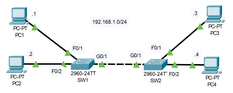
Instructions
PC1 pings PC3. What messages will be sent over the network & which devices will receive them?
Ping PC3 192.168.1.3 from PC1 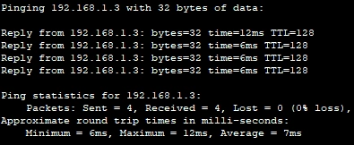
ARP Process
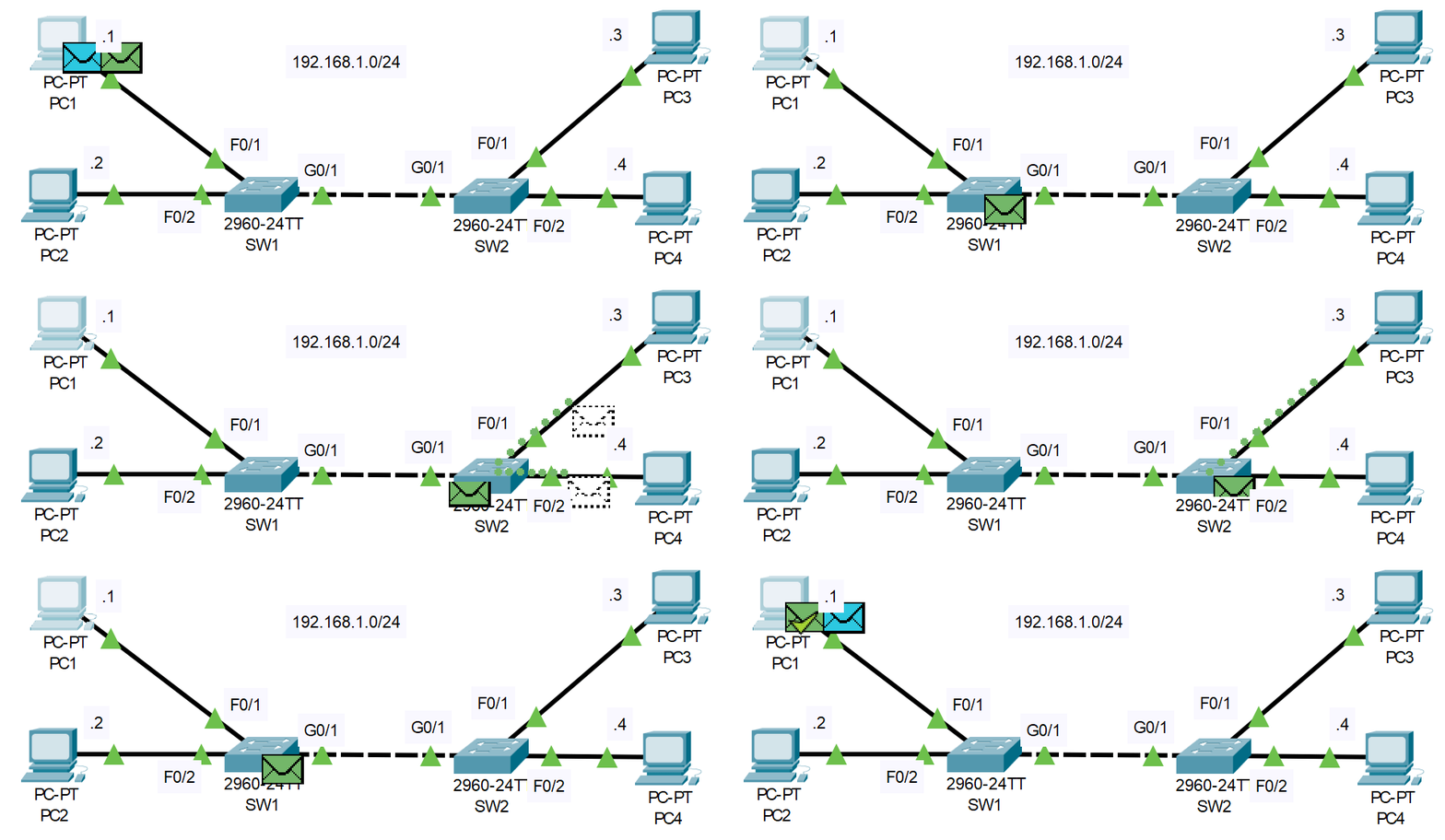
PC1sends an ICMP message to192.168.1.3PC1does not know the MAC address of PC3 so ARP is constructed for PC3's IP addressSW1adds PC1 to MAC address table ->SW1broadcasts the ARP request out all ports except sourcePC2processes frame and drops it because it's not for the destination IPSW2adds PC1 to MAC address table ->SW2broadcasts request out all ports except sourcePC4dropsPC3updates it's ARP table ->PC3sends out a reply with MAC address
- Frame is sent to
SW2->SW1->PC1 PC1updates it's ARP table
Ping Process
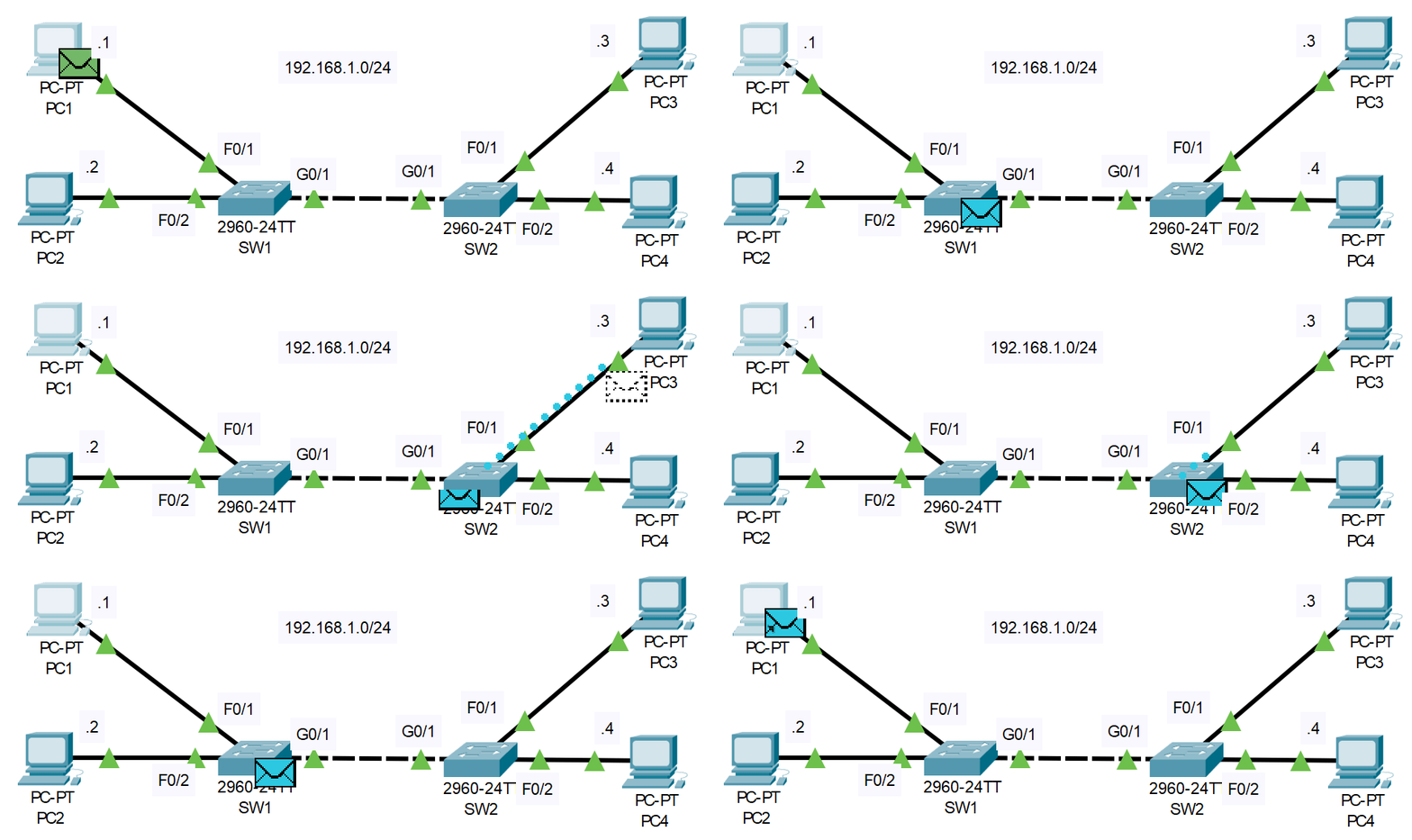
PC1sends out ICMP echo requestPC1has the MAC address ofPC3from ARP table so it sets a destination MAC address and sends it outSW1receives frame ->SW1sees that it has destination MAC address in it's MAC table and sends it out port G0/1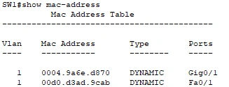
SW2receives frame ->SW2sees that it has destination MAC address in it's MAC table and sends it out port F0/1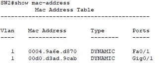
PC3receives frame -> decapsulates PDU from frame -> decapsulates packet because it was destined for this IPPC3processes the ICMP packet & sends an echo reply to the IP address ofPC1- Frame is sent to
SW2->SW1->PC1 PC1decapsulates packet & receives the echo reply message